MEASURING AN OPTICAL PULSAR LIGHT CURVE
USING A STROBING TECHNIQUE
TELESCOPE MOUNTED STROBE WHEEL
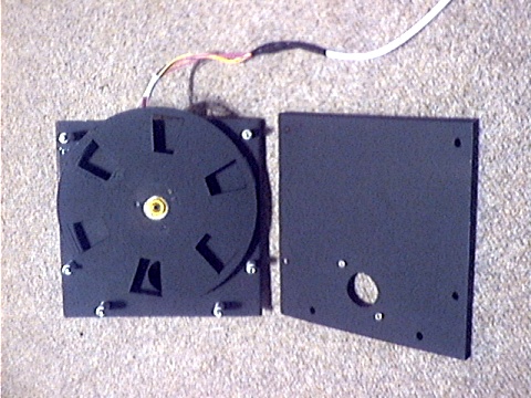
To match the 30 Hz pulse rate of the pulsar, a 150mm diameter strobe wheel with 6 windows per revolution and an open to closed ratio of 1:2 has been built. Taking the pulse per revolution of the stepper motor into account, the required pulse rate of approximately 240 Hz (which can be set to a resolution of 0.1Hz) is obtained from the computer sound card. The output from the sound card drives the stepper motor driver circuit.
INTERNALS OF STROBE WHEEL ASSEMBLY
The strobe wheel is made from a light, rigid plastic sheet to reduce weight and minimise vibration. It is driven directly from the stepper motor. The strobe wheel assembly is bolted between the VC200L OTA visual back and the flip mirror. The camera is mounted on the outgoing side of the flip mirror. There is insufficient inward travel on the focusser to allow the use of a focal reducer so the standard focal length of 1800mm is used.
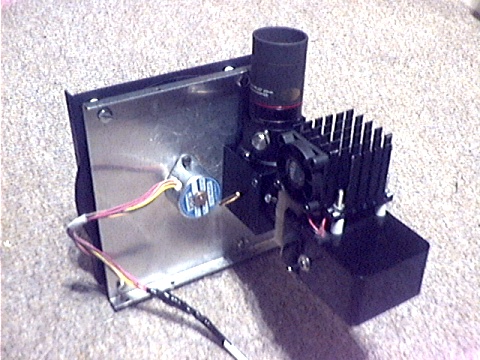
CAMERA AND FLIP MIRROR MOUNTED ON STROBE WHEEL ASSEMBLY
24th March 2003
BACK TO PULSAR DETECTION INTRODUCTION