SPECTROSCOPY
RETURN TO SPECTROSCOPY
INTRODUCTION
The
Star Analyser
200
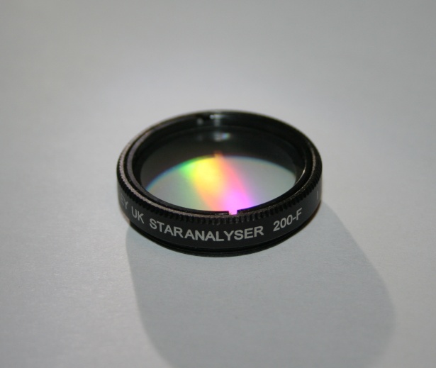
The
Star Analyser SA200-F Concept
I
developed the original SA100 Star Analyser back in 2005 and since then it has
introduced several thousand amateur astronomers worldwide to the fascinating
field of spectroscopy. Over this period, the equipment used by amateurs has
evolved with larger aperture telescopes, bigger camera sensors and close coupled
filter wheels becoming more common.
The Star Analyser SA200 model was developed in 2014 with these users in
mind.
Using
the same Paton Hawksley high efficiency blazed diffraction grating technology as
the SA100, but with double the line density, the SA200 gives approximately the same length of
spectrum but at half the spacing from the camera sensor.
A
new low profile design allows the SA200-F to be used with a wider
range of filter wheel models and when used with a threaded collar can
potentially even be adapted for use in wheels designed for unmounted drop in
filters.
Examples
of the SA200 used in other
applications
Although
the main application of the SA200 is where the optimum spacing between grating
and camera sensor for the SA100 cannot be achieved, there are other applications
where the SA200 can be used to advantage.
The SA200 used as an objective grating
mounted in front of a camera lens
The SA200 used in the SEPSA eyepiece
projection slit spectrograph
A “junk box” fully collimated slit
spectrograph design using the SA200
Is
the SA200 a replacement for the
SA100?
Most
definitely not! For a given length
of spectrum the SA100 still marginally out performs the SA200 when used in the
standard configuration between the telescope and camera. For most users the SA100 is expected to
continue to be the model of choice, particularly for those using cameras with
small sensors, giving optimum performance for example with the SA100 mounted on
the camera nosepiece. In circumstances though where it is not practical to
achieve the optimum spacing from the camera sensor required for the SA100, the
SA200 gives an opportunity to improve performance.
What
is the optimum spacing and when should the SA200 be used
?
The
on line calculator www.patonhawksley.co.uk/calculator
(ticking the box for the SA200 or SA100) will calculate the dispersion (in
Angstrom/pixel) for a given equipment setup. This figure, combined with the
guidelines and help messages there gives an indication of the optimum distance
between the grating and camera sensor and whether the SA100 or SA200 is the
best choice. For many applications the SA100 gives the best performance but to
see where the SA200 can in certain circumstances be the better choice we can
delve into the theory behind the calculator in a bit more
detail.
The
maximum resolution achievable using the simple arrangement of a grating mounted
in the converging beam in front of the camera sensor is limited by various
optical factors to around 30-40 Angstrom. To be able to achieve this resolution
however the spectrum must first be spread out sufficiently to overcome two other
limitations.
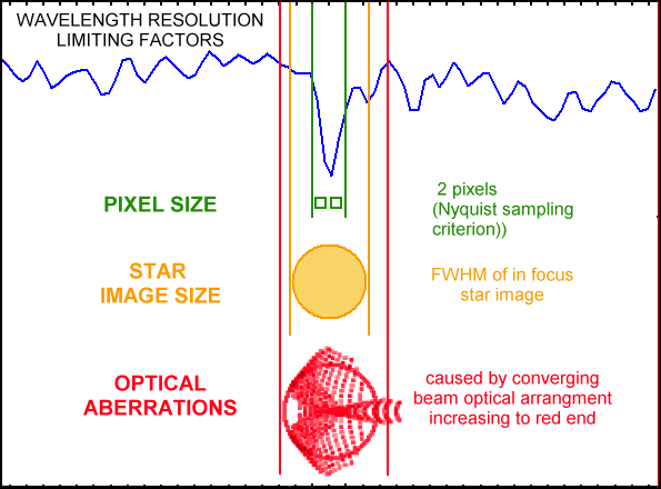
Firstly
the resolution cannot be better than 2 pixels (The Nyquist sampling condition)
so to achieve a resolution of say 36A, we need to aim for18A/pixel or less.
For
typical amateur setups, it is usually the second condition which is harder to
meet and the following examples illustrate typical situations where the SA200
can help.
The
Star Analyser mounted in a filter
wheel
Filter
wheels are typically positioned as close to the camera sensor as possible to
minimise vignetting in astrophotography. This distance is usually less than
optimum for the SA100, limiting the spectrum resolution. Consider for example the spectrum below
of P Cygni (in red), taken with an SA100 mounted in a filter wheel 30 mm from
the camera sensor (an ATIK ATK314L+ camera with 1390 x 1038 x 6.45um pixels) The
telescope is a 280mm SCT at f10.
Seeing was ~2 arcsec, giving a star image size of 4
pixels.
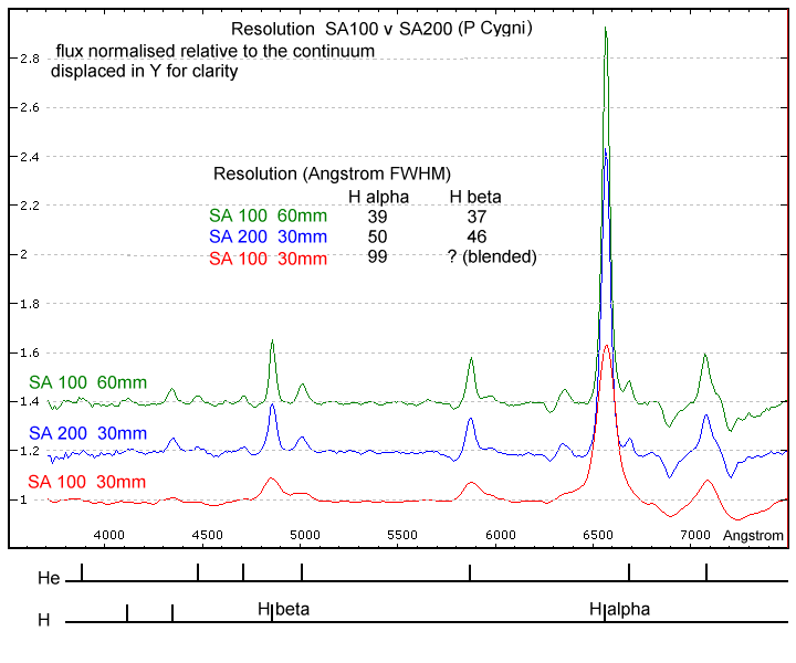
If
however the SA200 is used instead, (blue spectrum) then the dispersion becomes
11 A/pixel and the resolution limit based on star image size limit is now ~ 44A,
close to the maximum potential resolution using the Star Analyser, confirmed by
the increased detail seen in the blue spectrum.
(The
green spectrum shows the result of achieving the same dispersion but this time
with an SA100 at double the distance. The resulting resolution is slightly
higher than when using the SA200 at half the distance, confirming that provided
the optimum distance can be achieved using the SA100 then this remains the best
option)
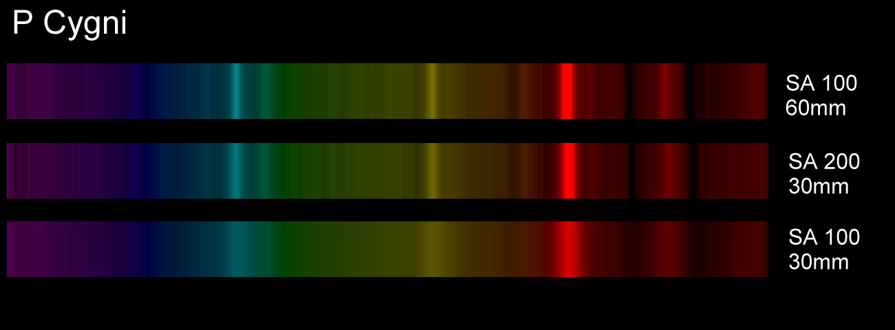
Below
are the same results represented as colourised 2D spectrum images
The
Star Analyser on a large
telescope
Consider
a setup consisting of a 400mm aperture f10 telescope equipped with a camera with
a large sensor (eg a Kodak KAF 3200
with 2184 x 1472 x 6.8um pixels) and seeing of 2.5 arcsec (7.1 pixels
FWHM).
Using
the calculator we find that to meet the star image size condition of 36/7.1 = 5A/pixel we would need a spacing of 135mm for the SA100. Such a large
distance may be difficult to arrange, whereas the SA200 mounted at half the
distance (68mm) would be easier to accommodate and would give similar
performance.
Note
that at this high dispersion, a large sensor is needed to fit the zero order and
spectrum in the frame and the effect of field curvature will be greater making
it more difficult to keep the full length of the spectrum in focus.
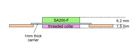
Mounting
the SA200-F in filter wheels
With a significantly lower profile (7.7mm
total height, 5.2mm above the thread compared with 11.2mm total height,
7.7mm above the thread for the SA100), the SA200-F can be mounted in filter
wheels designed for 1.25 inch filters without risk of fouling the wheel housing.
(Note that the low profile design means that, unlike the SA100, there is no
thread available above the grating to screw on other accessories.) The SA200 can
be aligned with the camera sensor and held in the correct orientation for
example with PTFE tape on the thread or a spot of hot melt adhesive.
Provided
there is sufficient clearance, the SA200 can also be mounted in wheels designed
to take unmounted drop in filters.
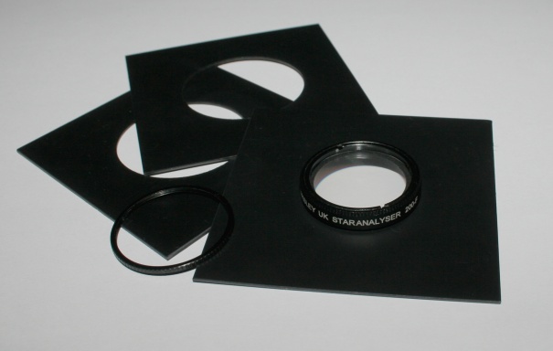
An internally threaded collar fixes the SA200-F in position in a carrier
plate, for example made from black styrene sheet (plasticard), cut to the size
of the unmounted filter. The grating can be orientated correctly and held in
position by the threaded collar.
A
similar technique can also be used to mount the SA200 in a blank 2 inch filter
cell for wheels designed for 2 inch screw in filters
Alternatively
a 2 inch diameter 1.25 inch to M48 threaded adapter for example from Teleskop Service or Agena Astro or 365
Astronomy or ZWO can be used provided there is enough
clearance.
(Note
that, since the light cone from the star is only dispersed into a spectrum
beyond the grating, any vignetting of the field due to the smaller aperture of
the SA200, compared with filters used for imaging, is not a problem provided the
zero order image of the star is placed within the unvignetted
area.)