PC USB CONTROL OF THE LHIRES III NEON
CALIBRATION LAMP
(Updated 19 Aug 2008 - Alternative servo power
source)
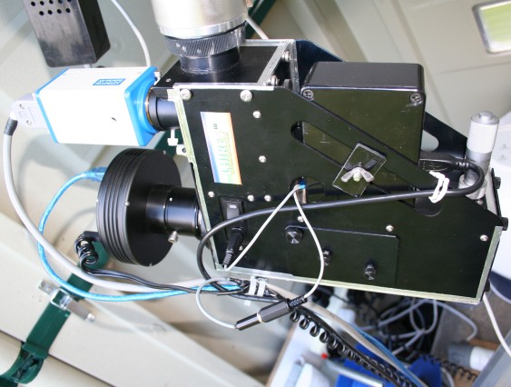
Neon Controller Installed on LHIRES
III
Control is from the PC via the USB cable. (It ended up
running very close to the grating micrometer adjuster!)
The neon
position is controlled by a servo coupled to the rear screw of the neon
shaft.
The 12v power to the neon is separately controlled. This
means the switched off neon can be moved into the beam to act as
a shutter for taking darks.
No permanent modification to the LHIRES
is needed except for replacing the cross head screw on the rear of
the neon axle with a hexagon socket head screw to give a more
positive drive.
The box sits on the top plate of the LHIRES.
It is slid into engagement with the neon axle and clamped to
the side of the LHIRES with the wing
nut.
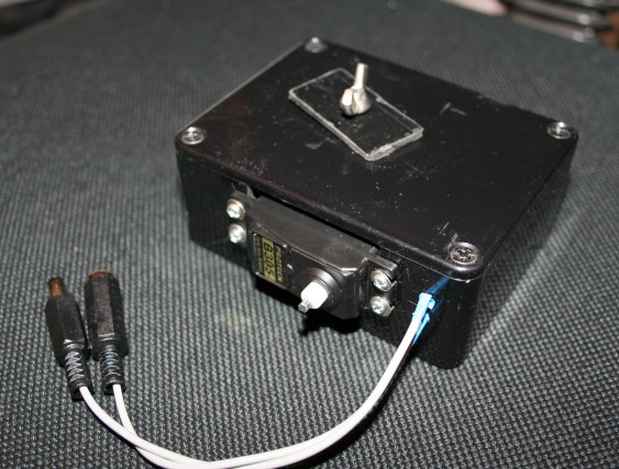
Neon Controller
The servo and circuitry was built into a small
(MB2) project box
The Protech
B305 servo gives plenty of torque to move the neon. The
mounting screws are in slotted holes to allow adjustment to align the
drive shaft to the neon axle.
The drive shaft is short length cut
from a hexagonal allen key. The servo drive shaft was drilled out
until the key was a push fit. It was then glued into
position
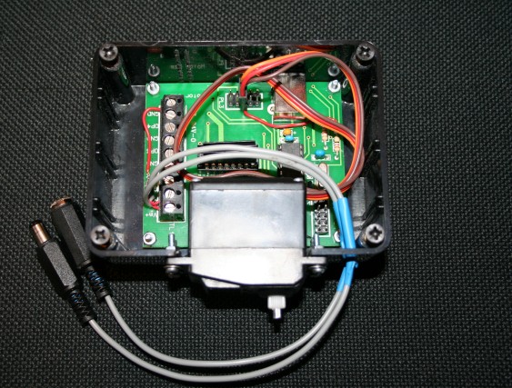
Controller Circuitry
A "Motor Bee" control
board is used to control the servo and neon 12v power. It is based on
a PIC IC with a built in USB interface and can control the servo and 4
high power variable outputs, one of which is used to switch the neon
supply. It also has several digital inputs and outputs so has capacity for
future expansion.
The servo was originally powered from the USB 5V
supply. (The red wire from the servo plug to the 5V
side of a resistor on the board.) This needed a powered USB hub to
supply enough current. The controller has now been modified
to include a 5V voltage regulator (7805)
providing the power from the 12v neon supply instead. (Roll your mouse over the image to see the new
layout)
Control Software
The servo calibration is done by positioning the neon shaft half way between the "in" and "out" positions and setting the servo to its neutral position (128) before engaging the servo drive shaft. (The neon shaft is rotated slightly until the hexagonal drive shaft engages). The servo settings are then found which rotates the neon until it is just off the "in" and "out" stops, so that the servo is not under continuous load in either position. (100 and 170 for my setup. Check that the neon position is correct using the guide camera image.)
The neon power is switched on and off with the output 1 set to 255 (maximum)